Reverse Engineering a Chip (or well, a GDS)
A writeup of Jane Street's ASIC challenge
I've been waiting a couple of weeks to publish this!! Jane Street put out a GDS reverse engineering challenge in early August which looked pretty fun, so I jumped on it pretty much immediately. They did, however, embargo solutions until the deadline of September 4th, hence why this is getting posted so late.
Background
To briefly summarize the problem statement:
Here's a GDSII layout file. If we sent this to a fab, they'd etch it into silicon and make a chip.
Figure out what the proposed chip does, and what input sequence makes the
successoutput toggle high. Then report the ASCII string associated with that solution.
The ASCII generator wasn't considered part of the "interesting" circuit, which is why you'll see it mostly ignored in the journey below. I also gloss over the top-level IO throughout the writeup, but it's really quite bare:
module puzzle (
    input wire rst_n,
    input wire clk,
    input wire I,
    input wire enable,
    output logic success
);
AI was used throughout the process to do some of the ickier things that were considered legal – investigating open-source tools and writing throwaway scripts for the most part. There were two cases where an underspecified prompt caused AI to go a little too far in the solving, but those "discoveries" were promptly wiped (off the hard disk and from my memory), and I continued solving the puzzle on my own. I've noted where the AI made such oversteps and as I hope you will agree, I don't think it compromises the authenticity of my solution too much!
The first bit of my solve involved generating a Verilog netlist from the input GDS file – this provides conectivity of all the low-level standard cells (NAND, OR, MUX, FF) used in the design, and can be used in simulation tools to test correctness. My input pattern was mostly determined by manually observing/rewriting the netlist and running test-simulations to figure out what each of the individual sections of the GDS did, and how they would affect success. The observed behaviors were used to compile a set of rules the input stimulus would have to obey, which was then used to construct a simple state-space exploration model.
I made a fairly critical oversight early in the process that you could just use Yosys' sat tool on an elaborated netlist to pull out the final solution. As a result, this is a significantly more manual solution than most of the other ones that I've seen people online post (ahead-of-embargo) as well as the methods AI has suggested during an after-solve postmortem. However, it has the neat side effect that I pretty much know exactly what every hardware structure and comb chain in the GDS is, to enough of a degree that I think the reverse-engineering here could be used to write behavioral HDL yielding an equivalent post-synth netlist.
The rest of this writeup was actually the e-journal I used to reason about the puzzle as I solved it, as well as a bunch of screenshots and relevant snippets I collected to document the journey. As a result, there's definitely a lot of jumping-between-ideas and backtracking, nor is the prose necessarily that of a "polished postmortem". I would read the rest of this blog post as more of a novel than as a "solution document" as a result (or fast-forward to the end). Enjoy!
Making Sense of the Thing
I first pulled up the GDS in KLayout. It's a bit dense, so I toggled out the upper regions and hid all the tap/via/internal cells. Left with a much nicer view! Approximately equivalent to the image shown in the repo, actually.
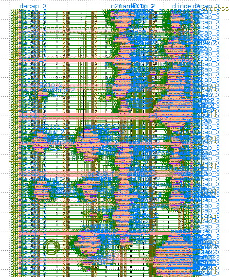
Now want to identify block boundaries and reverse-engineer them by hand. Makes life easier, and we can look at smaller parts of the design one-by-one. Manually enumerated those in the table below. Little slog-y, but should return dividends later.
Regions of Interest
Here are the bounding boxes of all the distinctly observed islands in the layout.
| No. | Thing | Coord 1 | Coord 2 |
|---|---|---|---|
| ~ | Funny coord box | (0, -48) | (200, -54) |
| 1 | Top Left Flop | (29, 207) | (41, 195) |
| 2 | Upper Behemoth | (100, 289) | (132, 179) |
| 3 | Top Right | (164, 290) | (184, 262) |
| 4 | Middle Left | (17.93, 168) | (44, 140) |
| 5 | Middle Right | (54.88, 170) | (101, 130) |
| 6 | Lower Middle Left | (24, 113.5) | (44, 89) |
| 7 | Lower Middle Right | (70, 116) | (93, 91) |
| 8 | Lower Behemoth | (106, 154) | (135, 41) |
| 9 | Bottom Left | (65, 64.3) | (96, 18) |
| 10 | Bottom Right | (150, 60) | (195, 10) |
Easter Egg 1
The internal boxes at the bottom of the layout looked pretty weird. This was what I called "Funny coord box" above.
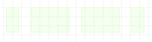
At first I thought it was spelling something out in ASCII, and thought I'd do some coordinate division later on when I had a GDS parser written. I ended up hiding the cells for some reason and saw the same region again anew.

That looks… almost suspiciously like morse code. There were three different spacings I spotted – tiny, sub-1-box-medium, and greater-than-two-boxes. So symbol, letter, word spacings, I suppose? Can't hurt to dump it into an online translator.
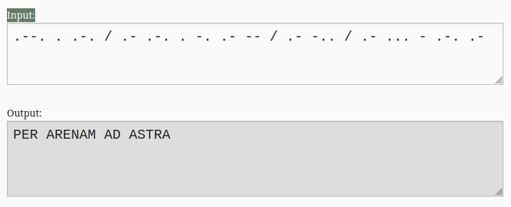
Honestly I thought it was gibberish or that I was typing it in wrong until I saw the ad. At that point I was pretty sure it was Latin. Sure enough:
Through the sand to the stars.
Very fitting for silicon! Though I would have expected it from SpaceX, not JS.
Python-ing to Look at Cells
Okay bounding boxes have been constructed. Python time. Sub-block elaboration may be overkill, but it seems like the easiest way for me to write out a behavioral equivalent for analysis by inspection.
I'd been using AI to search for tools and how to set up SKY130-type stuff, but I now used it to vibe-code a small script that uses the klayout python library to parse the GDS file. Did some basic accounting to make sure that the boxes I'd be inspecting didn't have overlapping cells, and that only non-trivial cells (no clkbuf, tap, via, etc.) would be recorded. I also specifically wanted to see what cells were not captured by the boxes. Looking at the output of said script:
$ ./polygons.py # done this way bc venv in eshell is hard
sky130_fd_sc_hd__clkbuf_4 r0 97.52,70.72
sky130_fd_sc_hd__clkbuf_8 r180 102.58,76.16
sky130_fd_sc_hd__clkbuf_4 r0 146.28,174.08
sky130_fd_sc_hd__clkbuf_16 r0 104.88,163.2
sky130_fd_sc_hd__clkbuf_8 m90 91.08,76.16
sky130_fd_sc_hd__clkbuf_4 r0 83.26,76.16
Okay, only clock buffers were ignored. Splendid!
I updated the script to also dump all the cell names. A lot of these look like familiar formulations from intro to VLSI, but I did notice that I hadn't accounted for diodes in my ignore list.
sky130_fd_sc_hd__diode_2: 9
Again for functional modeling reasons, I'm going to map this down as a passthrough or an ignore. Additionally, I didn't see any tristate buffers or other non-bistate cells, so going forwards I assume this is a "well-behaved" digital circuit, without any odd inout-like properties.
At this point, the hopeful approach is that given the functional descriptions of each cell, which we can find in the library files, and identifying net connectivity, we can form some sort of high-level netlist to reverse-engineer.
At this point it appears that there are 494 cells in the mystery components of the layout. That seems fairly tractable to create a basic netlist of, and then try to make sense of the netlist directly. I suspect adders will be the most annoying primitive to identify by inspection.
Assembling Sub-Block Connectivity
So turns out the GDS doesn't actually record net connectivity, which makes sense, it's basically just a shape database. The authors did retain the cell instances and pin labels though, which is very kind of them. This makes life a little bit easier.
So the hope is this: we basically harvest the PDK connectivity rules to "flatten" nets, dump a really verbose netlist, and expand our script to flatten it for us iteratively.
When initially prompting GPT to ask it about the capabilities of the KLayout library to accomplish the net flattening task, it somehow figured out the mappings from layer names to metal layers and via layers? Not too sure how, I guess it did it by looking at the PDK files that I had in the same directory?
Turns out that it found a conveniently provided gds_layers.csv in the skywater PDK which shows exactly what the mapping is from semantic names to numerical names. So we can now start to form nets since we know what the metal and connectivity layers are in the GDS.
So gds_layers.csv shows that the Skywater PDK has exactly 5 metal layers. Looking at KLayout, it seems like Metals 4 and 5 are mostly used for routing VDD and GND (they are forming power stripes).
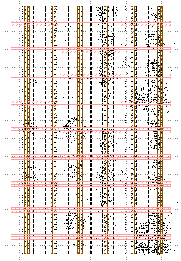
The li1 layer is for local interconnect, so I assume that to be within the cell. Which means only metals 1-3 and the vias connecting them together need to be traced for net connectivity, with some floating checks done afterwards to fill in gaps.
Additionally, we can treat "funny" instances (clkbuf, diode) as passthroughs/net retention blocks for our behavioral equivalent. GPT has been proompted to get an initial connectivity/net tracing script. I've requested that it treat clock buffers and diodes as "pass-through" points, so the net is retained through them.
I found some KLayout SKY130 collateral on github which was pretty useful, it almost single-handedly allows me to probe nets in KLayout now since it provides the layer connectivity descriptions.
Turns out when I asked GPT to do net tracing it started trying to build its own netlist/connectivity extractor from the PDK files which is maybe another reason to not let AI run on its own for too long…
Round 2
Pivoted a little bit. Turns out that KLayout has this nifty feature that lets you export netlist connectivity in a file format called L2N, and Klayout's PyPi package has support for reading that in directly (rather than reforming connectivity in Python). So now (~9:14PM) new approach is reading in that L2N and correlating it with the GDS we read in via a Python script.
The initial script prototype is done at 9:27 after some back-and-forth! New script clocks in at only 270 lines, vs. the ~900 that GPT tried to write over the previous pass (yikes). But it's pretty useful – given one of our boxes, we can now see this handy breakdown:
$ ./simple_nettrace.py --box 1
Box 1 (29, 195, 41, 207)
3 netlist instances (+1 contracted), 8 signal nets: 1 internal, 7 boundary

Instances:
  $4180 sky130_fd_sc_hd__dfrtp_2 .RESET_B(rst_n), .Q($563),
    .CLK(clk [physical $421]), .D($573)
  $4600 sky130_fd_sc_hd__a31o_2 .X($573), .A3($193),
    .A2($284), .A1($289), .B1($563)
  $4716 sky130_fd_sc_hd__and2b_2 .A_N($563), .B(enable), .X($193)

Contracted/omitted physical-only instances:
  $4713 sky130_fd_sc_hd__diode_2 (diode-load)

Internal nets:
  $573: $4180.D, $4600.X

Boundary nets:
  [input] rst_n: $4180.RESET_B; top-level port rst_n; boxes 2 (22 endpoints),
        3 (3 endpoints), 4 (4 endpoints), 5 (13 endpoints), 6 (4 endpoints),
        7 (3 endpoints), 8 (22 endpoints), 9 (8 endpoints); obox (8 endpoints)
  [input] clk: $4180.CLK; top-level port clk; boxes 2 (22 endpoints),
        3 (3 endpoints), 4 (4 endpoints), 5 (13 endpoints), 6 (4 endpoints),
        7 (3 endpoints), 8 (22 endpoints), 9 (8 endpoints);
  [output] $193: $4600.A3, $4716.X; boxes 2 (18 endpoints),...
  ...
Inputs and outputs can be determined for a block by checking the PDK to see if any connected pins of instances within the box is an output. This makes it a lot easier to build up Verilog-esque modules.
Back-Corrections
After digging a little more, I found this package from Efabless that provides SKY130 support for KLayout, and seems to be more recently maintained. KLayout immediately becomes much better labeled and more usable by installing it.
There is a mild annoyance in that pins are no longer annotated with their name on cells, so I had to go back and correct the script to map pin numbers onto pin names and look at direction from that. But I guess that's not all too bad, in the grand scheme of things (especially when AI helps the process along).
Verilog Emission
The end of the GDS-to-verilog reverse engineering is in sight! We can use the boundary net annotation, instance list, and internal nets emitted by simple_nettrace.py to emit Verilog netlists pretty easily. When asked to generate a python script that does this, GPT was able to do it in under 2 minutes. Here is Box 1 (Top Left Flop), as an example:
`default_nettype none
// Source: /vault/asic-puzzle-2026/efabless.l2n
// Box: (29, 195, 41, 207)
module box_1 (
    input wire rst_n,
    input wire clk,
    input wire net285,
    input wire net290,
    input wire enable,
    output wire net193,
    output wire net569
);

    wire net579;

    sky130_fd_sc_hd__dfrtp_2 u4180 (
        .RESET_B(rst_n),
        .Q(net569),
        .CLK(clk),
        .D(net579)
    );

    sky130_fd_sc_hd__a31o_2 u4640 (
        .X(net579),
        .A3(net193),
        .A2(net285),
        .A1(net290),
        .B1(net569)
    );

    sky130_fd_sc_hd__and2b_2 u4756 (
        .A_N(net569),
        .B(enable),
        .X(net193)
    );

endmodule
`default_nettype wire
For readability's sake, I did want to make the output a bit more human-friendly. Using the reset conditions and documentation in Liberty files and the PDK resources, we can elaborate common gates and blocks (resettable DFFs, AND/OR/XOR) into proper verilog directives with assign statements or always_ff statements. Typically I would err towards having the DFF block as an instantiation (habits from past work), but I'm not used to the terminology being used here to denote the DFF types. So the same simple block from before will look like this instead:
`default_nettype none
// Source: /vault/asic-puzzle-2026/efabless.l2n
// Box: (29, 195, 41, 207)
module box_1 (
    input wire rst_n,
    input wire clk,
    input wire net285,
    input wire net290,
    input wire enable,
    output wire net193,
    output logic net569
);

    wire net579;

    // $4180 sky130_fd_sc_hd__dfrtp_2
    always_ff @(posedge clk or negedge rst_n) begin : ff_u4180
        if (!rst_n)
            net569 <= 1'b0;
        else
            net569 <= net579;
    end

    sky130_fd_sc_hd__a31o_2 u4640 (
        .X(net579),
        .A3(net193),
        .A2(net285),
        .A1(net290),
        .B1(net569)
    );

    // $4756 sky130_fd_sc_hd__and2b_2
    assign net193 = (~(net569) & enable);

endmodule
`default_nettype wire
At this point, we've done enough for readability that we can start working on actually deciphering some boxes! Though I do reserve the right to go back and add more optimization passes/lowering for readability should anything be too complex.
E2E Verification Pass
As a sanity/correctness check, the tooling used to generate Verilog netlists was also used on the warmup exercise, then compared with the reference netlists provided. Since the design is smaller and the source is already available (hence the goal is comparison, less-so optimizing for decipherability), I did so in a single shot rather than selecting regions of interest. Cell count matched, resets matched the original source, but the file being 450 lines of mixed instantiations and behavioral verilog made it less than ideal to debug.
The largest box in our design (Upper Behemoth) seems to be even longer in line length than the export of warmup, so we may need to do some similarity analysis for the large blocks to help our line of attack.
Deciphering: Pass 1
I figure this is best done by looking at each box, and trying to figure out how they relate?
Box 1, the upper left flop, is fairly simple. The entire module was shown earlier!
There is a single flip flop that resets to 0, with an update function described as the AND of 3 inputs from other boxes or the value of the flop itself. The design pattern here suggests some sort of flag, I imagine? Since one of the AND inputs is simply the flop not being set yet and enable being high, the set condition relies on the two middle-left blocks, both of which are on the smaller end in area. The two salient outputs from this module are:
flag(net569)active_flagn(net193), which indicates that the flag is not raised but the module is active
At this point, I think that there's enough Verilog and enough opaque signals that a partial rewriting approach may be prudent. That is to say, renaming signals to more semantically readable counterparts as a way to understand the logic better.
Shift Register Search
I noticed that the warmup had utilized a shift register. Searching for the same graph pattern in the netlist, it turned out that Box 5 had a set of chained flops with the same control inputs. Go figure! Honestly this was one of those things where I just had an idea and had GPT write throwaway scripts to confirm it.
This reduces down Box 5 to a 12-bit shift register logging past values of I, with the select logic to advance based on active_flagn and some lean surrounding logic. Mapping it down to a known construct immediately accounts for 12/80 FFs in the design, which is good headway!
Box 5's only outputs are to Box 3, which emits success, so my best guess at this time is that the logic here implements some check for a "win condition", so to speak.
Pass 2: More Verilog Reading/Rewriting
With the simplifications performed, the only other flop in Box 5 ($5342) seems to be another flag with a set condition based on the input being high and a compound gate. This flag's output path is also an inversion of its flop value, so probably another fulfillment condition. Tracing the assert terms of the set condition back:
(I & (SR[10] | (SR[9] & n330) | (n326 & (SR[11] | SR[0]))
Both nets still in this expression are from Box 7, so there's no perfect closed form here. Both nets, unfortunately, are long compound expressions:
assign net330 = (net73 | net90 | ~(net177) | ~(net8));
assign net326 = (net73 | net90 | net177 | net8 );
The expressions here are dangerously close though, so I guess this is something else input-dependent.
I started by looking at net73, which is a flip-flop in Box 4. With some DeMorgan's law and rewriting, we end up with this:
// $4861 sky130_fd_sc_hd__dfrtp_2
always_ff @(posedge clk or negedge rst_n) begin : ff_u4861
    if (!rst_n)
        net73 <= 1'b0;
    else
        net73 <= ~net290 & (net73 ^ active_flagn);
end
This ends up looking a bit odd, since depending on the value of net290 this value could be oscillatory?
assign net290 = (~(net73) & ~(net90) & net177 & net8);
I guess part of the reason this net is a bit odd is because there is fanout to other boxes?
FF Arrays
FF arrays are pretty common, so I was curious if there were any big ones that had shared enables, similar to the shift register. Outside of the SR we already found, Boxes 2 and 8 each contain 22 different flops that all have the same clock, reset, and enable condition – I guess that at least partially explains why they're so large!
Starting with Box 2, there's a group of 7 sticky flops that all share a similar setup condition. For now, we can group them as a module array for simplification's sake.
sky130_fd_sc_hd__a31o_2 u_a31o_array_660 [6:0] (
    .X(a31o_array_660),
    .A3({net551, net624, net721, net710, net682, net683, net655}),
    .A2({7{active_flagn}}),
    .A1({7{I}}),
    .B1(ff_array_667)
);

sky130_fd_sc_hd__o21a_2 u_o21a_array_667 [6:0] (
    .X(ff_array_667_d),
    .B1(a31o_array_660),
    .A2({net528, net623, net722, net706, net690, net670, net658}),
    .A1({net527, net619, net718, net701, net686, net669, net652})
);

always_ff @(posedge clk or negedge rst_n) begin : ff_array_667_regs
    if (!rst_n)
        ff_array_667 <= '0;
    else
        ff_array_667 <= ff_array_667_d;
end
This rewrite pares down what was a 600 line file down to ~400. Simplification!
Looking at the array of inputs on A3 of u_a31o_array_660 in particular, every signal seems to be a transformation of 4 nets:
assign net721 = (~(net73) & ~(net90) & net177 & net8);
assign net551 = ~(net8 | net73 | net177 | net90);
net73 is the flag from Box 4. net90 is another FF from Box 4.
Working Backwards
I needed a change of pace/new approach since the FF arrays were messing with me, so I wanted to trace back what the exact conditions for success raising were, and maybe do some brute-forcing on the underlying conditions. Some rewriting gets you to this much nicer expression of the success flag.
// $218 sky130_fd_sc_hd__dfrtp_2
// asserts on flag raise when net79 and net469 go both high
always_ff @(posedge clk or negedge rst_n) begin : ff_u218
    if (!rst_n)
        success <= 1'b0;
    else
        success <= success | (flag & ~flag_r & net79 & net469);
end
The problem is that if you go into Box 9 in the bottom right, where net79 comes from, you end up with this mess of an expression, at least when flattened.
// $6768 sky130_fd_sc_hd__and3_2
assign net79 = ((net62 & net71 & net61 & net60) &
                (net82 & net98 & net97 & net96) &
                (net226 & net77 & net118));
Though for what it's worth, each of the intermediate signals were not consumed elsewhere. So I'm inclined to suspect some sort of reduction tree operation here (equality check?). Especially since it's on 11 inputs, which is our magic array number!
Even more specifically, this particular reduction is actually an AND across 11 distinct inputs from Box 8, which contained an FF array. My spidey senses say that the FF array is probably tracking part of the win condition as status flags, so to speak.
Box 5, the source of net469 actually has its own version of this same reduction network.
// $5002 sky130_fd_sc_hd__and3_2
// rename to "box_2_reduction".
assign net469 = ((net663 & net443 & net463 & net461) &
                 (net591 & net449 & net465 & net462) &
                 (net459 & net457 & net441));
The inputs of this are all out of Box 2, from what I can tell.
So at this point my hypothesis is that the "behemoths" are two control state bitmasks which are then AND-reduced by boxes 9 and 5. Those reductions are then AND-ed again to form the final success condition.
So either by static analysis or comb-testing, we now need to figure out how to force the 11-bit vectors coming out of Boxes 2 and 8 to go high.
Additionally, this rewrite of the reduction tree actually gets Box 5 down to only 2 concrete components.
- The shift register from earlier.
- The reduction tree for the status flops in Box 8 (Lower Behemoth).
So we have a much better idea now of the purposes of Box 5 and Box 3 (the success determinant). Things are taking shape!
Analyzing Box 2 to Box 5
Clearly individual boxes aren't giving us perfect functional separation, so I want to instead focus on the signal paths now. In this case, how the 11-signal-array in Box 8 is being generated and passed to Box 5.
Looking at the array FF breakdown we generated earlier, it doesn't immediately seem like the flop signals are being directly passed into the output ports. There's some weird indirection happening between different sets of FLOPs.
With some rewriting, I was able to restructure the group of 4-input NANDs from before as this expression instead.
assign ff_array_667_transform  = {
    ~(net8 | net73 | net90 | net177),
    (net8 & ~(net73) & ~(net90) & net177),
    (~(net8) & net73 & ~(net90) & net177),
    (net8 & net73 & ~(net90) & ~(net177)),
    (net8 & ~(net73) & net90 & ~(net177)),
    (~(net8) & net73 & net90 & ~(net177)),
    (net8 & net73 & net90 & ~(net177))
};
7/16 combinations have been enumerated of 4 outputs from Box 4, so my next point of investigation if this is fruitful will probably be going to figure out what these mean semantically (or what inputs can impact them).
Anyway, turns out that this transform directly pipes into another array NAND4s:
assign ff_array_667_nand =
    ~({7{I & active_flagn}} & ff_array_667 & ff_array_667_transform );
Each of the signals in this array, is used in one place and one place only… and that is to "set" an array of flags. The array of flags we identified earlier. Full circle!!
always_ff @(posedge clk or negedge rst_n) begin : ff_array_667_nand_r_regs
    if (!rst_n)
        ff_array_667_nand_r <= '0;
    else
        ff_array_667_nand_r <=
            ff_array_667_nand_r | ~ff_array_667_nand;
end
There are now a number of nets that follow the form:
// $1255 sky130_fd_sc_hd__and2b_2
assign net459 = (~(ff_array_667[3]) & ff_array_667_nand_r[3]);
These comprise 7/11 nets that are being passed into Box 5 for the AND reduction. Another bitmask computation!
// box 2
assign ff_array_667_to_box5 = ~ff_array_667 & ff_array_667_nand_r;

// box 5
assign box2_reduction =
      (&ff_array_667_to_box5) & net443 & net457 & net462 & net591;
This gets our upper behemoth down from an original 600 lines down to only 280!
Looking at other points in the file, turns out that there are other NAND4 gates computing another 4 combinations of the 4 Box 4 inputs. There are also duplicate nets – 4 different computations of ~(I & active_flagn). We can compute another transform bitmask!
assign ff_array_575_common = ~(I & active_flagn);
assign ff_array_575_transform = {
    (~(net8) | net73 | net90 | net177),
    (net8 | net73 | ~(net90) | net177),
    (net8 | net73 | net90 | ~(net177)),
    (net8 | ~(net73) | net90 | net177)
};
assign ff_array_575_condition =
    ff_array_575_transform | {4{ff_array_575_common}};
This ends up piping into an array of 4 FFs, albeit a little indirectly. I didn't actually spot it myself, when I asked GPT to help run a truth table on the above transformation it found the following rewrite of the 4-flop-array we grouped earlier.
assign ff_array_575_o21a_a2 = ~ff_array_575_condition;
assign ff_array_575_o21a_b1 =
    {net597, net641, net699, net576} |
    ~ff_array_575 | ff_array_575_condition;

sky130_fd_sc_hd__o21a_2 u_o21a_array_575 [3:0] (
    .X(ff_array_575_d),
    .B1(ff_array_575_o21a_b1),
    .A2(ff_array_575_o21a_a2),
    .A1(ff_array_575)
);

always_ff @(posedge clk or negedge rst_n) begin : ff_array_575_regs
    if (!rst_n)
        ff_array_575 <= '0;
    else
        ff_array_575 <= ff_array_575_d;
end
Looking at the 4 signals that are still not vectorized, those turn out to be a sticky array as well. Their "set" condition actually inherits from the same one used here. So we can get rid of some more individual signals in this module!
Box 4's Weird Quartet
At this point we have a set of sticky flops that are triggering on combinations of 4 specific signals coming out of Box 4. On intuition, this feels like comparison with a set of numbers? Like indices, almost. So I'd first like to check if we can consider the 4 signals in Box 4 to be a counter of some sort.
On inspection, the 4 nets are in fact flops! I created a small submodule that pulls out only the nets attached to them, and that treats active_flagn as a simple input. This should isolate them enough that we can see what their update logic is.
On another inspection, it turns out that Box 4 has… exactly one input, and outputs its FFs to a couple of other modules. So the test harness is approximately equivalent to the box itself. And upon observing a waveform, we see that Box 4 is, in fact, a counter. The 4 outputs form a counter that is mod-11, which would explain why we see 11-flop-arrays being special in Boxes 2 and 8.
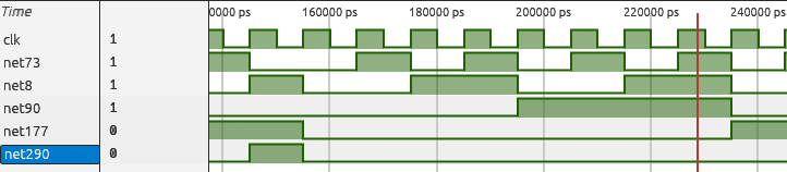
In retrospect it's a little unfortunate that we didn't just simulate some random data through the top-level as soon as we had Verilog emitted into submodules, as we probably would have seen the counter advancing! Though without the context that these are interrelated, I'm not sure I would have spotted it in real-time with ungrouped flip-flops.
Importantly, we now know the correct order of the outputs of Box 4 – this in turn means that we can much more easily group relevant logic and comparators in other blocks!
Additionally, net290, which used to be cryptic:
// $4657 sky130_fd_sc_hd__and4bb_2
assign net290 = (~(net73) & ~(net90) & net177 & net8);
This is just checking if the counter has hit 10! Similar comparisons and simplifications can be made across the design as a result. The transform arrays in box 2 can be converted to fairly simple constant-comparisons with counter!
assign ff_array_667_transform = {
    (counter == 4'd0),
    (counter == 4'd10),
    (counter == 4'd9),
    (counter == 4'd3),
    (counter == 4'd6),
    (counter == 4'd5),
    (counter == 4'd7)
};

assign ff_array_575_transform = {
    ~(counter == 4'd2),
    ~(counter == 4'd4),
    ~(counter == 4'd8),
    ~(counter == 4'd1)
};
We now also have enough information about the I/O that we can actually simulate box_4 and box_2 connected to each other, albeit while supplying some dummy information.
Analysis of Box 2 from Simulation+Rewriting
After some additional rewriting, Upper Behemoth is now down to under 140 lines. Importantly, turns out that the weird cascaded register structure for 667 encodes whether a given mod-11 position in the input stream sees the value 1 more than once. The other register array tracks whether the position has seen a 1-bit once or more than twice. Hence the transmitted data to box 5 is actually:
// you have seen 2 "1" bits in a given position
assign ff_array_667_to_box5 =
    ~ff_array_667 & ff_array_667_nand_r;
The 575 array does the same thing, though it seems to have been optimized differently. So overall, Box 2 (Upper Behemoth) is performing a check on if there is a total of 2 ones across the mod-11 indices of the bitstring. This was confirmed experimentally in simulation.

Going back up to Box 5, there is another success component we have not yet debugged, which is net421. It needs to be low for success to fire. It is yet another sticky FF, set by the following chain:
assign set_421 = net442 & active_flagn & I;

sky130_fd_sc_hd__a22o_2 u4991 (
    .B1(net326),
    .B2(shift_reg[11]),
    .A1(net326),
    .A2(shift_reg[0]),
    .X(net423)
);
sky130_fd_sc_hd__a221o_2 u5198 (
    .B2(shift_reg[10]),
    .C1(net423),
    .B1(1'b1),
    .A1(net330),
    .A2(shift_reg[9]),
    .X(net442)
);
net326 and net330 used to be a bit obscure, but we can now see a very simple representation of them!
// is counter nonzero?
assign net326 = (counter[0] | counter[1] | counter[2] | counter[3]);

// Is counter not 10?
assign net330 = (counter[0] | counter[2] | ~(counter[3]) | ~(counter[1]));
Flattening the logic a bit:
assign net423 = (|counter) & (shift_reg[11] | shift_reg[0]);
assign net442 = net423 | shift_reg[10] | (counter != 4'd10 & shift_reg[9]);
We now have the three things we do not want to see in our sequence, particularly when we see a new 1 in the stream.
- 1 should not be in the 0th/11th position, unless we are on a clean cycle
- 1 can only be in the 9th position when the counter has also shifted in exactly 10 bits
- You cannot shift in a 1 when there is already a 1 in position 10
- Read: Cannot have two 1s exactly 10 bits apart
This is a bit hard to formulate into some understandable property of input data, at least naively, so I'm going to come back to this… For now, I'll treat it as an explicit constraint to solve against for my input data later. Maybe this gains more relevance once we know the expected input length(s)?
Analyzing the Lower Behemoth's Inputs
The next step of our puzzle is figuring out what pattern is being verified by Lower Behemoth. From our previous exploration, we found that the unexplored chain from Lower Behemoth is as follows:
Box 6 -> Box 10 -> Box 8 -> Box 9 -> Box 3
Looking at Box 10, which seems to act as a controller for LB, it's purely combinational. Everything it does is a transform on counter and some outputs from Box 6, which we can now try to characterize.
Box 6 also seems oddly simple in terms of inputs – it takes only the active tracker from Box 1 and the modulo sentinel from Box 4. The box contains 4 FFs, all of which are exported as outputs. There also seems to be some chaining, so if it looks like a counter…

I guess it talks like a counter too! Box 6 consists of a 4-bit counter that counts the number of times the mod-11 counter has looped around while active. It increments on cycles where counter_hit_10 is set out of Box 4. Just like the original counter, epoch_counter is also modulo-11. It's possible that there's some 11-by-11 grid abstraction at play, but I'm not too sure yet.
Additionally, something we can see in the waveform and confirm analytically is that net285 is checking whether the epoch counter has hit 10.
// $6467 sky130_fd_sc_hd__nand3b_2
assign net286 = ~(~(net101) & net88 & net87); // three flops!

// $6606 sky130_fd_sc_hd__nor2_2
assign net285 = ~(net74 | net286);
So net285 is effectively an epoch_counter_hit_10 signal. We didn't rewrite Box 6 as much as some of the previous signals, but we've effectively characterized the outputs, and can consider this one solved. This signal is only sent to Box 1, so we can go back and try to reason about it again.
// $4180 sky130_fd_sc_hd__dfrtp_2
always_ff @(posedge clk or negedge rst_n) begin : ff_u4180
    if (!rst_n)
        flag <= 1'b0;
    else
        flag <= net579;
end

sky130_fd_sc_hd__a31o_2 u4640 (
    .X(net579),
    .A3(active_flagn),
    .A2(epoch_counter_hit_10),
    .A1(counter_hit_10),
    .B1(flag)
);

// $4756 sky130_fd_sc_hd__and2b_2
assign active_flagn = (~(flag) & enable);
Box 1 has now been mostly populated with legible signal names! It should now be clear that the flag is set after both counters have hit 10, meaning that 121 input elements were processed. This also better contextualizes one of the expressions we wanted to solve in Box 3!
// $433 sky130_fd_sc_hd__and4b_2
assign net708 = (~(flag_r) & flag & box8_reduction & box2_reduction);
This signal is checking for the cycle after the 121st element is registered, and that the reduction checks from Box 8 and Box 2 are both fulfilled. Nice!
Box 7's Last Output
Since Box 3 is mostly solved, the main blocker on it (outside the weird condition) is actually just figuring out what the last output out of Box 7 was. After some staring at the verilog, I realized that {net310, net329} formed a saturating counter of the number of high inputs collected over a cycle of counter.

The output condition is the inversion of a sticky flop, and after some rearranging I was able to get a much nicer set of expressions for its assert condition.
assign set_condition = (active_flagn & counter_hit_10 & net323);
assign net323 = sat_counter[1] ? net325 : net315;
assign net325 = (sat_counter[0] | I);
assign net315 = ~(sat_counter[0] & I);
Keep in mind that this flop constitutes an error condition! Thus, an explicit rule we must follow is that each group of 11 bits has no more than 2 ones. I was able to confirm this error condition by running some groups-of-11-bits through simulation and observing the assertion behavior. Together with the constraint from Box 5, this provides fairly strong row/column constraints.
Box 10 Index Mapping (and Easter Egg 2)
Box 10 ends up being a static transformation on the values of counter and epoch_counter – sadly I could not figure out by visual analysis what the meaning of the 4 outputs were in a waveform. That said, I did notice that the utilization pattern of the 4 signals in LB is fairly similar to the enumeration that was happening with the index-matching in upper behemoth!

Based on Box 2, the vector indices probably only go up to 10. So by process of elimination we can figure out which bit belongs in which bit position. We have the following constraints:
- The MSB will only be
1in cycles where there is at most another bit high (as 9/10 have two hot bits) - The bit at position 2 is mutually exclusive with the bit we determine to be the MSB, as we max out at 10
- Guess-and-check for the ordering of the 2 LSBs (search space is down from 24 combinations to 2!)
I asked AI to write a python script to convert the values of the relevant signals in a VCD dump into a CSV file so I could do this experiment. Writing a Python check to track maximum non-position one-bits on that data gives us the following:
net159: 2
net214: 1
net205: 2
net180: 2
Okay, so net214 is the MSB. Now for the mutex check, below is the output of an overlap accumulation (e.g when MSB is high, the corresponding index is also high).
net159, net214, net205, net180
[28, 55, 0, 6]
So the implication here is that net205 is most likely at position 2! At this point since there are only two possible bit-orderings, we can just plot an 11x11 grid with both possible orderings, and pick whichever makes more sense.
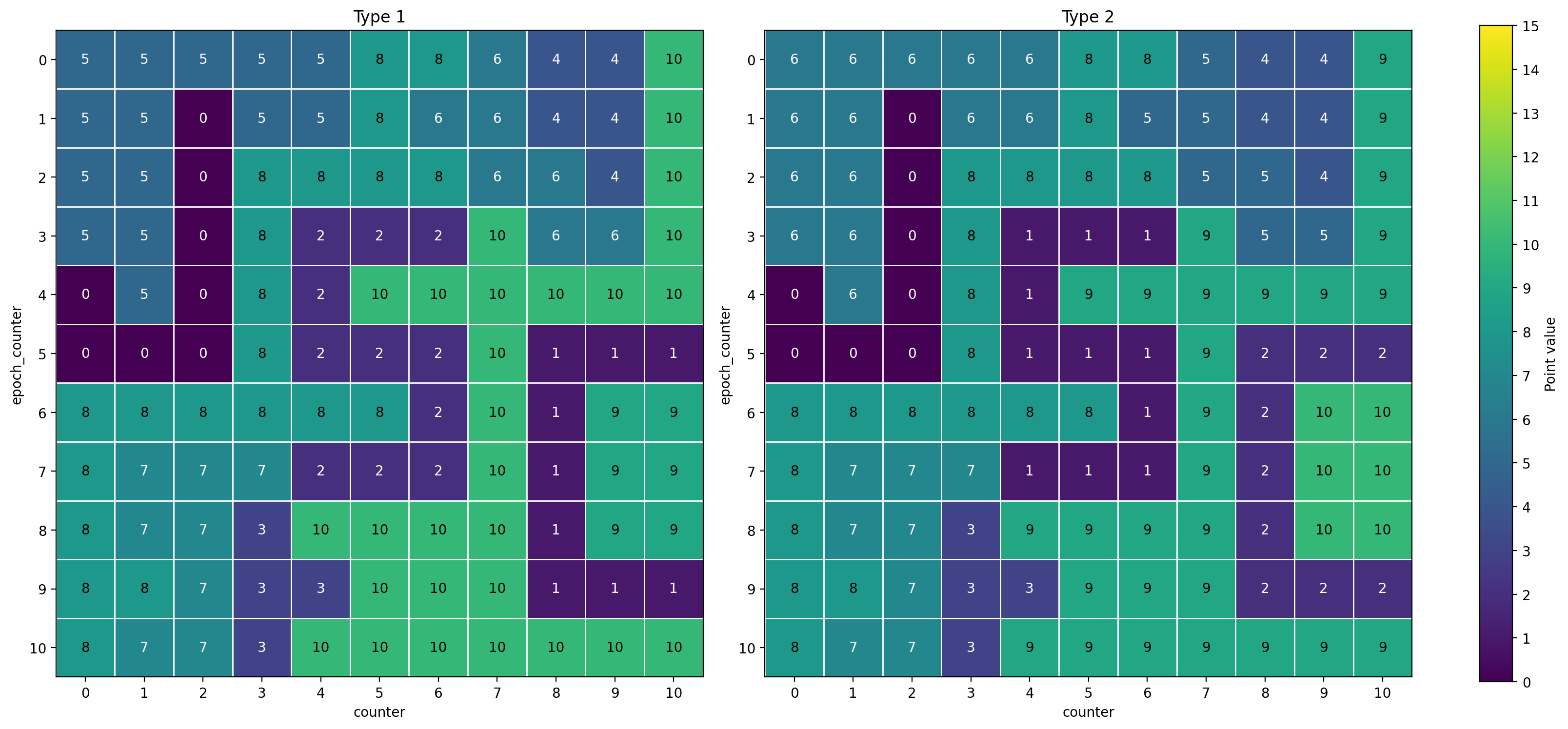
Jane Street Capital – very cool! Both mappings look about the same, so for no good reason I chose the alphanumerically ordered one.
assign magic_index = {net214, net205, net180, net159};
Note that under both schemes, we see that the assembled numbers encompass the range 0-10, meaning our index range assumptions for Box 8 should hold.
Attacking the Lower Behemoth
Based on the reduction and how upper behemoth shook out, it's likely that each index has independent tracking logic, with state updates not crossing across indices. Thus if we can reason about the constraints tracked set in one state FF, we should be able to generalize it to the other ones.
I picked an arbitrary select signal, and grouped together all its downstream gates into one region. I then did some mild rewriting, and stopped once I hit this point:
// $2563 sky130_fd_sc_hd__and4bb_2
// select signal
assign net399 = (~(magic_index[0]) & ~(magic_index[2]) &
                   magic_index[3] & magic_index[1]);

// $2285 sky130_fd_sc_hd__dfrtp_2
always_ff @(posedge clk or negedge rst_n) begin : ff_u2285
    if (!rst_n)
        net412 <= 1'b0;
    else
        net412 <= net412 | (active_cond & net408);
end

// $2572 sky130_fd_sc_hd__nand2b_2
assign net418 = ~(~(net412) & net425);

logic active_cond;
assign active_cond = I & active_flagn & net399;

// $2603 sky130_fd_sc_hd__nand4_2
assign net425 = ~(active_cond & net408);

// $2561 sky130_fd_sc_hd__dfrtp_2
always_ff @(posedge clk or negedge rst_n) begin : ff_u2561
    if (!rst_n)
        net408 <= 1'b0;
    else
        net408 <= (net412 | net425) & (active_cond | net408);
end
This looks remarkably similar to the saturating counter we saw in Box 2! However instead of incrementing based on position in the group of 11, the position is based on the stencil that we found earlier. I generated some test stimulus that placed 1s only when magic_index was set to 10, and was able to verify the sat counter behavior in simulation.

Now that we have the state machine behavior, we just need to figure out what the output behavior is from these FFs. The condition used this time is a little different than what was done in upper behemoth.
assign net118 = (~(net408) & net412);
So it seems like the 11 outputs of Box 8 are tracking whether specifically two indices per "magic index" are set to 1. We've successfully characterized Box 8, and with significantly less rewriting! We should now be able to return to Box 9 to figure out how the reduction pattern works.
Returning to Box 9
We should first take another look at the reduction we pulled out earlier.
// $6768 sky130_fd_sc_hd__and3_2
assign box8_reduction = ((net60 & net61 & net62 & net71) &
                (net82 & net96 & net97 & net98) &
                (net77 & net118 & net226));
It's a direct pass-in of each of the outputs from Box 8, so we don't need to do much more characterization on this path. The only loose end in the Box 8 chain is that of net156, Box 9's other output to Box 3 (the success generator)
// $6297 sky130_fd_sc_hd__and4_2
assign net156 = (net145 & net146 & net130 & net154);
This block has 8 registers in total, and they all seem to eventually funnel into this net. The inputs from Box 8 are only used for the reduction, and ignored in the rest of the module. So seems like that part of the equation has been nicely wrapped up in a bow.
The remaining inputs are just whether the module is active or not and the input… maybe there's another counter? To test, we can just spam 1s into the module and see what happens to the registers.

That instinct seems to have paid off! So the final output from this box is checking that the overall number of 1s in the input string has hit some target. We can rename signals to make the expressions more readable then unroll them. The waveform shows that the condition is looking for the counter to hit 22 (so solution has 22 nonzeros), but we should confirm this analytically as well.
// $6297 sky130_fd_sc_hd__and4_2
assign net156 = (bit_counter[1] & bit_counter[2] & bit_counter[4] & net154);

// $5612 sky130_fd_sc_hd__nor3_2
assign net154 = ~(bit_counter[5] | bit_counter[6] | net223);

// $5608 sky130_fd_sc_hd__or3_2
assign net223 = (bit_counter[0] | bit_counter[3] | bit_counter[7]);
Solved by 8'b00010110 = 8'd22. Very cool!
Revisiting Box 5's Odd Constraint
The only win condition we haven't actually semantically deciphered yet is net421 in Box 5. However, knowing that the solution is a 2D grid helps make sense of the weird equations from before.
assign net423 = (|counter) & (shift_reg[11] | shift_reg[0]);
                             // ^ purple
assign net442 = net423 | shift_reg[10] | (counter != 4'd10 & shift_reg[9]);
                         // ^ red        // ^ yellow
Since the comparison only occurs when I is high, we can consider this to be restrictions on where a 1 is allowed to be placed relative to other elements that came before it and in the previous row. First we should take a look at the "banned" elements when counter is nonzero. I'll lump shift_reg[9] into the graphic for visualization's sake. The black element is the current position of I in the grid, while the gray elements represent the window in the shift register. Illegal elements are color-coded as described in the block above.
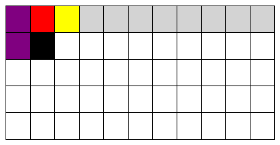
So all in all those constraints effectively create an adjacency rule. The nonzero counter bound is to make sure that elements that clip off to the left don't accidentally get flagged, and the restriction on shift_reg[9] is intended to prevent clipping off the right side.
Generating a Solution
So at this point I'm not totally sure exactly what the functional purpose of this chip is supposed to be architecturally speaking, but we can make some clear claims about what it's looking for and how we can provide that.
- The solution is a stream of 121 bits, containing 22 ones
- Each column needs to have two ones
- Each row needs to have two ones
- There is a stencil pattern requiring that each of its buckets is given two ones
- A "pixel" or element cannot be directly adjacent to another in the 2D plane
The stencil pattern is probably going to be the weirdest part of the output generation. So first things first, I want to generate a stimulus that will fulfill one of the behemoth's conditions – the column one is probably easiest. I wrote out a fairly simple map on paper of a pattern that has 2 nonzeros per column and 2 nonzeros per row.
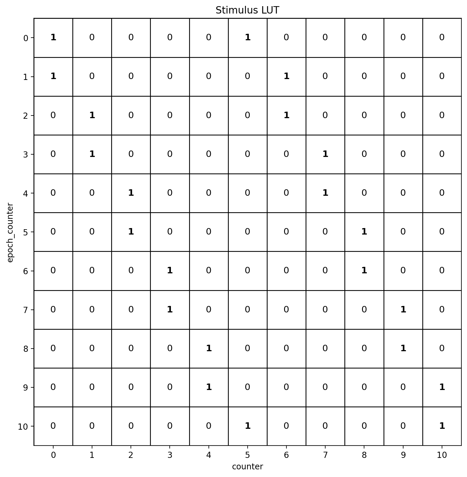
At this point we also know enough about the chip that we can start using a monolithic netlist of the entire design rather than submodule simulation. The simulation stack is the same, but the top-level harness changes to instantiate the monolithic netlist instead, including the output generator. A small python shim is used to serialize the stimulus array into a vector which is passed into Verilator via a CLI argument.
When run through Verilator, we see that the condition associated with Box 5 does go high – so at least some of our assumptions are correct!

At this point we can try to construct a more complete solution that fulfills all the constraints. I decided to go with a DFS state space solver, where various board configurations were considered state. Not the most elegant solution, but it works well enough. I did attempt a greedy approach at first, but couldn't figure out a good heuristic, and ended up with a fair number of local minima issues.
This spits out the following solution, annotated with stencil group numbers for clarity:
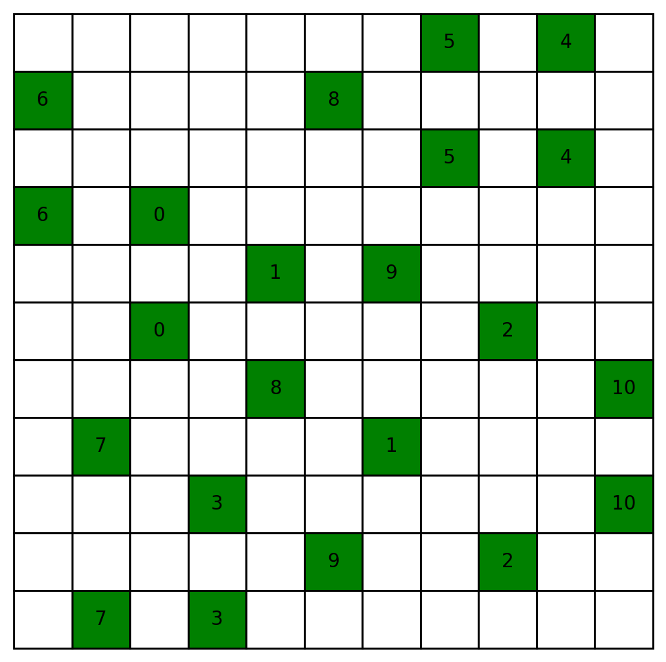
Lo and behold, it simulates correctly on the full design!!!

(* TWO STARS *)
Time Tracking
- Start: 5:30PM, 08/06
- Netlist Extraction: 10:30PM, 08/06
- Verilog Emission: 11:16PM, 08/06
- 5/10 Blocks Solved: 6AM, 08/07
- Done with Reverse Engineering: 4PM, 08/07
- State Space Solver/Full Solution: 5:10PM, 08/07
End-to-end, about 24 hours.
Hindsight is 20/20
I was hoping that keeping the gates intact would help with parsability, but I do think that some genuine logical optimization or flattening in the initial Verilog emission phase would have helped speed up the analysis and rewriting portions of the reverse engineering.
It's probably apparent that I realized this as the challenge went on, but at some point I started to rely on simulation a lot more for reverse engineering, and that ended up being the right move. The 8-bit counter, for example, is probably not something that I would have been able to hand-flatten or identify by observation. Breaking down the GDS into submodules was probably the right move though, as it made looking at all of the data easier. Fuzzing the submodules or giving them random data to pull out "connected" flip-flops in simulation rather than doing it analytically likely would have saved me a lot of time. I'm not sure it would have contributed to a full semantic reverse engineering as quickly, but it definitely would have produced a viable output faster.
Acknowledgements
Thank you to Tianchen "Jerry" Wang for a number of good suggestions when first trying to figure out how to recover Verilog from the provided GDS. Additionally, a huge thank you to the Jane Street team for putting this challenge together! I had an amazing time solving it. Good puzzles are hard to come by, and this is absolutely one of them.
And thank you, the reader, if you've made it this far! Enjoy a meme, free of charge.